The main purpose of medical imaging in conventional surgery is to make the diagnosis process earlier and more accurate. It provides insight into human body that is otherwise not visible to direct human vision. Four imaging modalities are commonly used for medical interventions:
X-ray and fluoroscopy,
Computed Tomography, or CT,
Magnetic resonance imaging, or MRI, and
Medical ultrasound, or US.
Medical imaging are used to visualize the target anatomy (e.g. a tumour) and formulate an intervention strategy (e.g. surgical resection or ablation, depending on the size and location) before the commencement of surgery. Due to the physics of each imaging modality, tissues are imaged with different characteristics based on their interaction with the physics of imaging. For example, X-ray have the ability to penetrate matter, but the amount of penetrating X-ray photons is material-dependent. When X-ray passes through matter, they
interact with atomic electrons,
interact with necleons,
interact with electric fields associated to atomic electrons and atomic nuclei.
Thus, denser materials, such as bone, attenuates X-ray photons much more than less-denser materials, such as soft-tissues, resulting on a brighter pixel intensity in X-ray imaging. Thus, while it is true that we are using medical imaging, and this is not a course on the physicals of medical imaging, you should nonetheless learn a bit about them.
Use of Medical Imaging for Surgical Interventions
In general, the use of medical imaging for surgical interventions can be broadly divided into the following categories (Elson & Yang (2010))
Pre-operative planning: to establish the operating target and its surrounding anatomical structures for planning out detailed access and operating trajectories; it also involves the establishment of framerelated coordinate systems based on anatomical or fiducial markers for linking the patient and imaging coordinate systems;
Intra-operative guidance: to provide real-time surgical guidance by providing anatomical and functional information about the operating site; increasingly, imaging is used in surgery for providing in situ tissue structure and function characterisation such that the direct outcome of the surgical procedure can be assessed. Augmented Reality (AR) is one important form of intra-operative guidance whereby the imaging data are combined with the exposed anatomical surface to provide see-through vision of the operating site;
Post-operative assessment: to assess the efficacy of the surgical procedure and the long-term benefit of therapeutic processes; for patients implanted with vessel prostheses or those who have undergone cancer surgery, serial image assessment provides an important monitoring tool for outcome management.
In other words, the pre-, intra-, and post-operative usage of medical imaging parallels with the surgical CAD, surgical CAM, and TQM as discussed before.
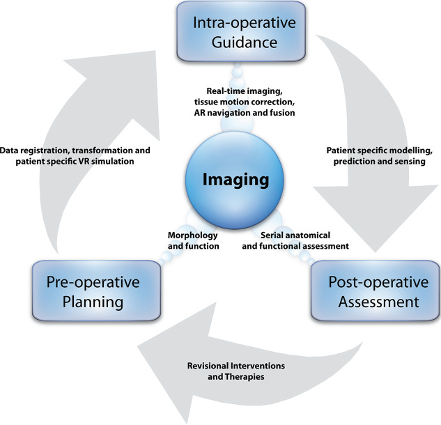
Figure 1:A shematic diagram showing how medical imaging is used for pre-operative planning, intra-operative guidance and post-operative assessment in surgery, as well as the key processes linking these components. Image courtesy of Elson & Yang (2010).
For the purpose of this course, thus, while you don’t need to understand the physics of medical imaging, you nonetheless need a basic understanding of what MRI, CT, US or Position emission tomography (PET) are showing, from an imaging processing point of view. Thereby you’ll develop an intution as to what algorithms are suitable for a particular types of medical imaging and their intended clinical applications.
Resolution
Perhaps one of the most mis-used terminology in medical imaging is the word resolutio. For example, we often talked that “A TV has a 4K resolution”, where is defined as a TV has pixels in the width and height, respectively. However, it is perhaps better termed as “pixel count”, as in how many pixel is used to represent an imaging, instead of an image resolution.
Resolution is defined as
Closest distance two points can be and still be perceived as distinct points
In this regard, resolution is measured as a distance (often in milli-metre), and not in pixels!
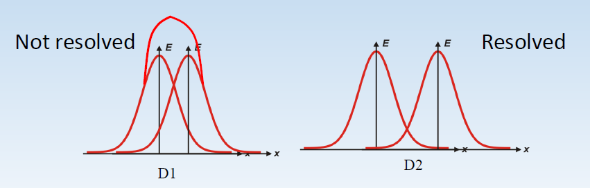
Figure 2:When a fiducial is images, it results in a point spread function (red curve) that blurs the image. The word resolution refers to the fact if two point spread function can be resolved (told apart).
In medical imaging, resolution is often expressed as:
Distance, e.g. Resolution of 0.5mm, or
line-pairs/mm: minimum of lines that can be resolved per milli-metre.
In this regard, resolution is measured as a distance (often in milli-metre), and not in pixels!
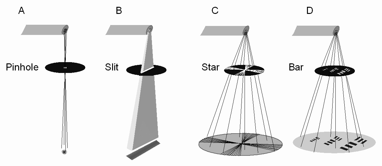
Figure 3:How image resolution can be measured. Image courtesy of Bushberg et al. (2020)
Medical Ultrasound
US has become the preferred non-invasive imaging modality due to their non-ionizing radiation nature and their ability to image soft tissues. The working principal of US are
time of flight, and
sound wave reflects and refracts when travelling from one medium to another (with different densities)
In this regard, US is able to image organ boundaries and internal organ structures, including changes caused by, as an example, tumour growths. The main advantages of US are the real-time nature, capable of live imaging (i.e. video), portability, and (relative) cost.
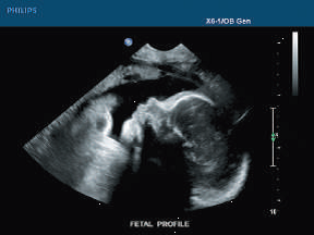
Figure 4:Cross-section US image of a fetus, image courtesy here, accessed on 2026-02-03.
For US imaging, the resolution scales as the inverse of the acoustic frequency, which for modern equipment is generally less than 1mm (MHz). However, as the acoustic frequency increases, the penetration depth decreases due to the increased absorption, leading to a trade-off between image resolution and penetration depth.
The main application of US is both functional and structural, used to image anatomy with motion (i.e. cardiac with beating heart) or flow (i.e. via Doppler ultrasonography for cardiovascular). US is widely used in cardiovascular, hepatobiliary, pancreatic, renal or gynaecological problems, or in obstetrics to visualise the foetus (Elson & Yang (2010)).
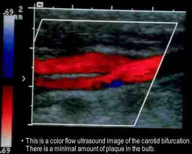
Figure 5:A Doppler ultrasound to visualize the direction and velocity of the blood flow.
3D Ultrasound
While most of the clinical ultrasound are 2D image modality, modern US in fact has 3D capability. There are several mechanisms to achieve 3D US, with real-time 3D US achievd by ultrasound transducer equipped with a matrix-array of piezoelectric elements.
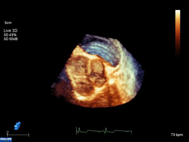
Figure 6:A 3D US volume depicting the Tricuspid valve at the right ventricle of the heart.
Compared to 2D US, 3D US in general has lower resolution and slower frame rate.
X-ray
X-rays are high-energy electromagnetic waves that only interact very weakly with tissue, although different tissues will absorb the radiation to varying degrees. Images of the radiation that has passed through the body can be recorded after the X-rays have directly or indirectly interacted with a phosphor screen that emits light. This light can be recorded on photographic film or a digital camera or can be amplifi ed by an image intensifier. X-rays imaging is the most common form of pre-operative planning, and in conventional radiology, the contrast in the images is generated by differences between soft tissue (mainly water), bone, fat and air or gas. This method is typically used for musculoskeletal imaging as bone absorbs X-rays more strongly than soft tissue, and the images can be used to detect fractures, tuberculosis of the spine, benign and malignant tumours, osteoarthritis, rheumatoid arthritis and gout. To improve the contrast available in X-rays imaging, iodine (for intravenous and intra-arterial angiography) or barium sulphate (for investigation of the GI tract) may be administered, as these atoms highly absorb X-rays.
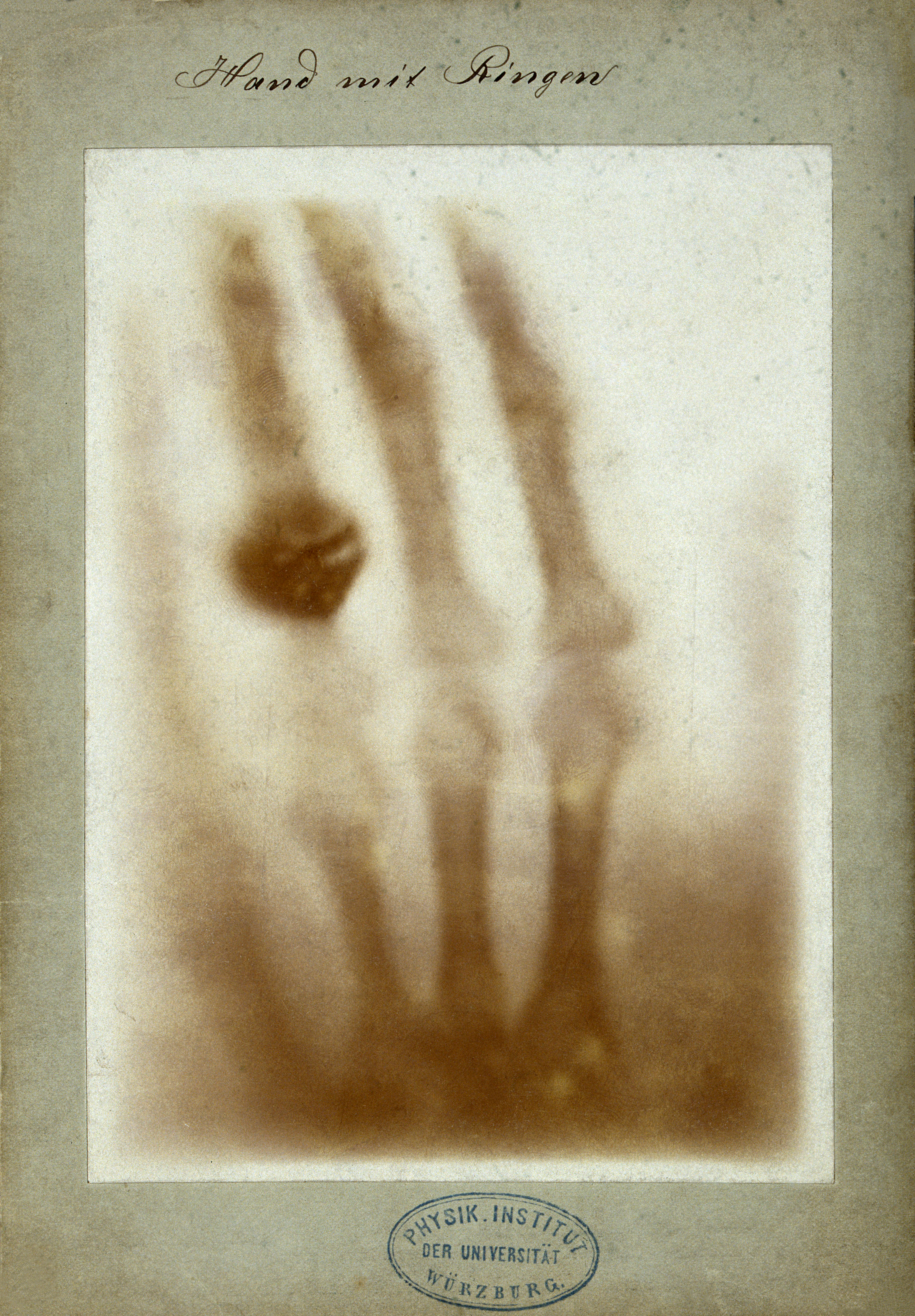
Figure 7:Considered as the first medical imaging, this is Hand mit Ringen (Hand with Rings): print of Wilhelm Röntgen’s first “medical” X-ray, of his wife’s hand, taken on 22 December 1895 and presented to Ludwig Zehnder of the Physik Institut, University of Freiburg, on 1 January 1896. Image courtesy of Wilhelm Röntgen, Public domain, via Wikimedia Commons, accessed here on 2026-02-03.
X-rays was discovered by Wilhelm Röntgen, a German Physics professor in 1895. Within weeks, on February 14, 1896, John Hall-Edwards used x-ray in a surgical operation. At the time though, the harmful impact of ionizing radiation to biological tissues was unknown, and Hall-Edwards’ interest in X-ray cost him his left arm due to advanced cancer.
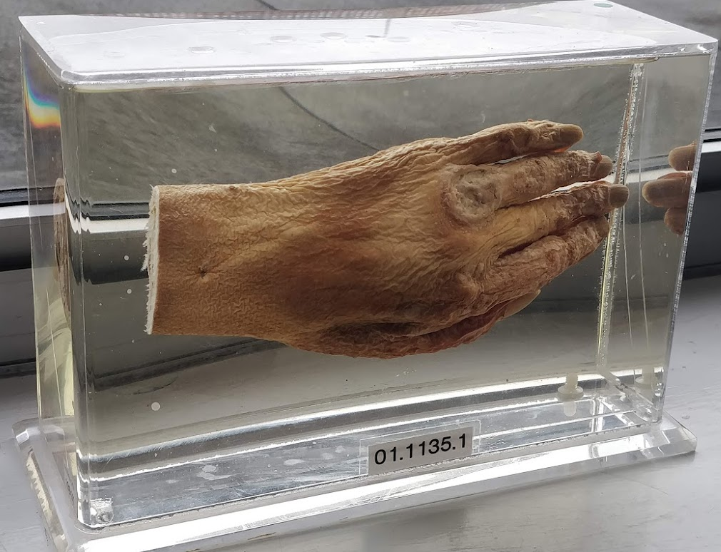
Figure 8:The amputated left hand of John Hall-Edwards, following extensive radiation damage. Image courtesy of Archon 2488, CC BY-SA 4.0, via Wikimedia Commons, accessed here on 2026-02-03.
Interpretation of X-ray image
The interpretation of the 2D projections produced in X-rays imaging can be difficult, especially in anatomically complicated structures and overlapping tissues, and it is common to use X-ray CT in these situations. As X-rays imaging is a function of the X-rays attenuation, it is important to remember that:
Attenuation is related to atomic number or electron density of atoms in beam path,
Most body tissues are carbon-, hydrogen-, oxygen-, and nitrogen- based, atomic masses of 12, 1, 16, and 14 respectively. There are traces of Calcium (40) and iron (56) as well.
In this regard, a transparent tissue between the X-ray source and image detector implies that more photons strike detector giving a bright image. Intermediate transparent causes gray image.
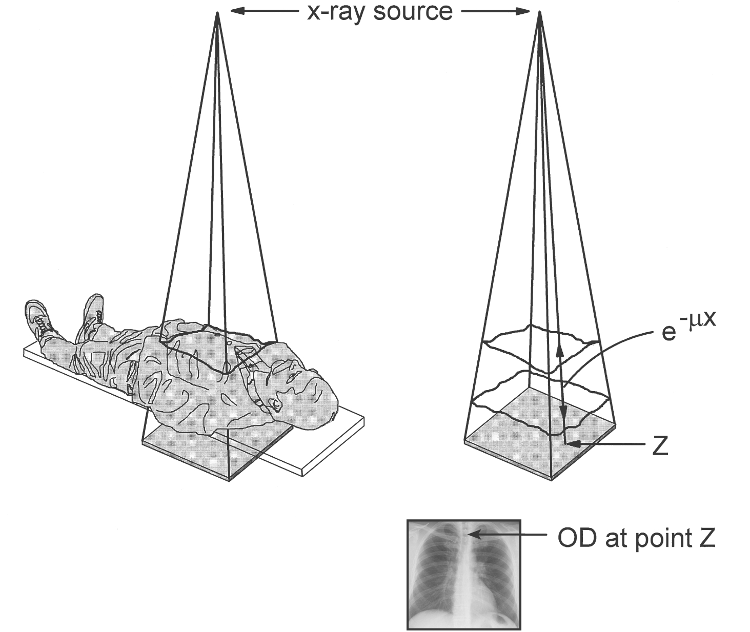
Figure 9:X-rays image is formed with an X-rays source and an image detector (beneath the patient). Image intensity at a point z depends on the x-ray attenuation of the X-rays beam within the tissue. Image courtesy of Bushberg et al. (2020)
X-ray systems
Catagorically, there are 2 types of X-ray imaging system:
Radiography that takes a single, stationary, X-rays image, and
Fluoroscopy, that uses low-dose X-rays and acquiring contineous (i.e. video) images. Fluoroscopy can be either stationary or is on a rotational platform.
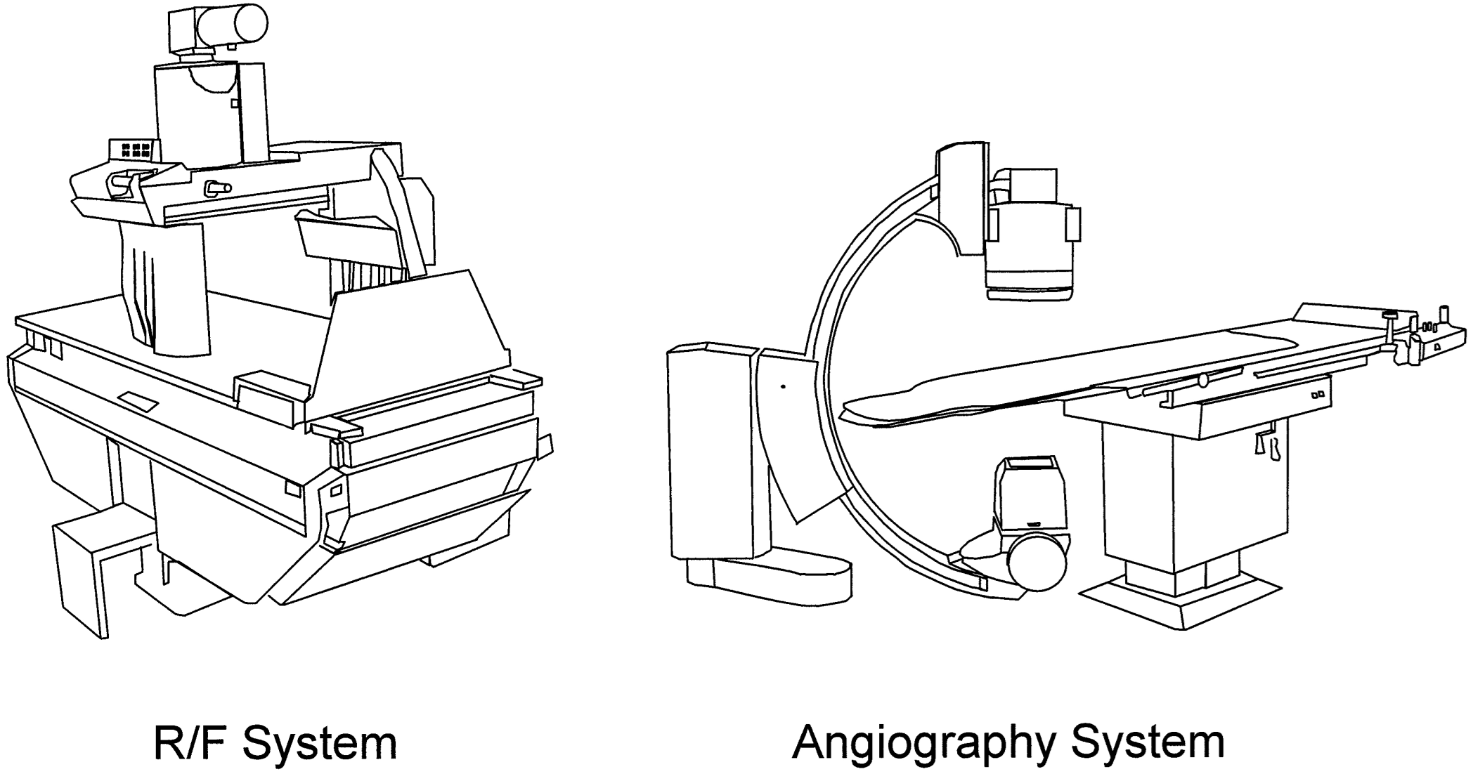
Figure 10:(perhaps old) X-ray imaging system. The Radiography (R/F) System take a stationary, single, x-ray image, where as the C-arm system has the x-ray source and detectors on a rotating platform that has the capability to take contineous images (i.e. video). Image courtesy of Bushberg et al. (2020)
Angiography
Angiography is a medical imaging techniques used to visualize the inside of blood vessels and organs of the body, performed by injecting a radio-opaque contrast agent into the blood vessels and imaging using X-ray based techniques such as fluoroscopy.
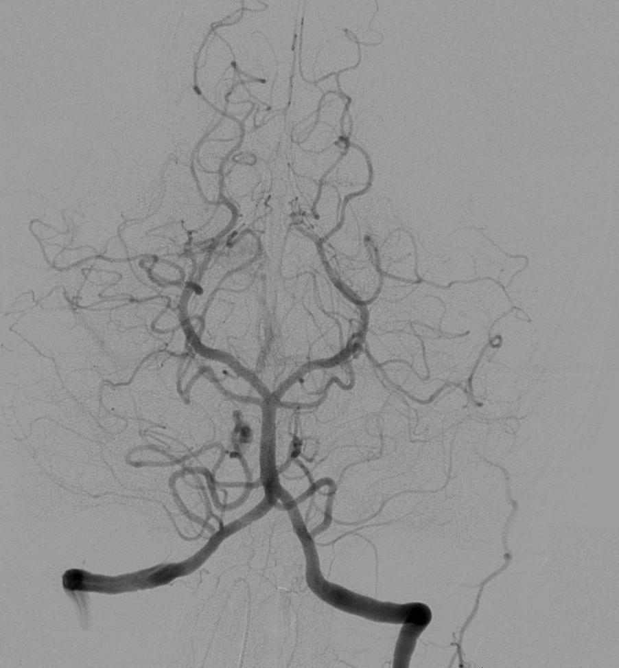
Figure 11:Cerebral angiography, injection in the left vertebral artery, with retrograde flow in the contralateral vertebral artery, the basilar artery and the posterior communicating artery. The posterior cerebral circulation can be seen, including the posterior part of the Circle of Willis. Image courtesy of Lipothymia, Public domain, via Wikimedia Commons, accessed here on 2026-02-04.
Computed Tomography
In CT, the absorption of the tissue is recorded as the X-ray source and a one-dimensional array of detectors are rotated around the patient’s body, resulting in a number of one-dimensional projections recorded at different orientations of the body (called sinograms).
In CT, the X-rays are collimated so that only a thin slice of the patient is probed during each acquisition. Image reconstruction can then be performed to create a cross-sectional image, where each pixel of the image represents the absorption of a given region of the crosssection. This whole procedure can then be repeated at different slice positions to build up a 3D volumetric model of the patient. Common applications of CT include investigations in staging of various tumours, calcifi cation, lung cancer, cerebral infarction, haemorrhage and abscesses, complex fractures, pulmonary diseases such as emboli and detection of acute and chronic pancreatitis.
The pixel intensity of a CT is measured in Hounsfield scale (HU), defined as:
where and are respectively the linear attenuation coefficients of water and air. In this regard, CT is calibrated with reference to water and other materials to ensure standardised response.
Scanning Geometry
Conceptually, a 2D CT image is acquired by rotating an X-ray source and detectors about the scanned object, and 3D CT volume is reconstructed from 2D CT image by translating the X-ray source and the detectors axially along the object. Modern CT geometry has the capability to acquire multiple slices per revolution, leading to shortened acqusition time and resuced slice thickness (improved axial resolution).
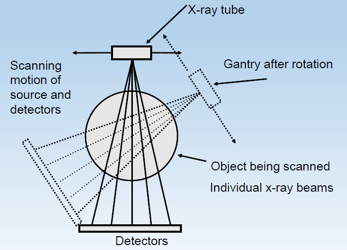
Figure 12:Scanning geometry of CT, Image courtesy of Prof. Terry M. Peters at Robarts Research Institute, Canada.
Resolution and Contrast
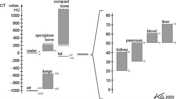
Figure 13:CT numbers (HU) of various tissues. Image courtesy of Bushberg et al. (2020)
Figure 13 lists the HU for verious tissue types. Notices that most of the soft-tissues, such as kidney and liver, have very similiar HU values. You should ask yourself why! That is to say, CT has very low image contrast for soft-tissues and thus one may not be able to differentiate soft-tissues of different types from CT easily.
The in-plane resolution of a CT image can be quite high, limited by the number of detectors. The out-of-plane resolution, i.e. the axial resolution, could be lower than that of the in-plane resolution, limited by the amount of translation of the translation used to move the object relative to the X-ray source and detectors. Modern CT scanners use in clinical setting are capable to achieve a resolution of or better.
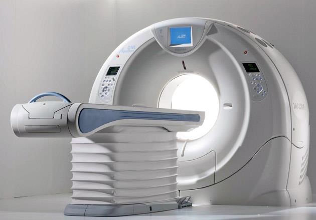
Figure 14:Toshiba Aquilion CT scanner, capable of scanning of 320 slices per rotation at 0.35 second per rotation.
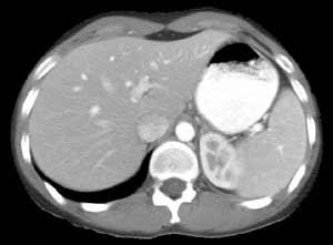
Figure 15:CT scan of a liver, Image courtesy of Prof. Terry M. Peters at Robarts Research Institute, Canada.
Magnetic Resonance Imaging
Magnetic Resonance Imaging (MRI) allows the density of nuclei in the tissue, particularly hydrogen found in water, to be imaged. The main advantages of MRI lie in the excellent soft tissue contrast it provides, the absence of absorption and shadow artefacts caused by the presence of bones and also the absence of ionising radiation required for CT/radionuclide methods. The intrinsic contrast of the MR signal can be programmed to reflect proton density and different relaxation effects of the tissue. It is emerging as an important tool for pre-operative planning because of its safety, versatility and the high-quality images it produces that allow accurate and reproducible quantification of structure and function such as blood flow and perfusion
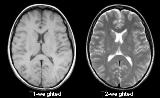
Figure 16:MRI scans of a head, demonstrating the same anatomy but imaged using different pulse sequence. Image courtesy of Prof. Terry M. Peters at Robarts Research Institute, Canada.
MRI System
While a MRI machine looks similar to a CT machine, having a round opening in the middle, internally they are quite different.
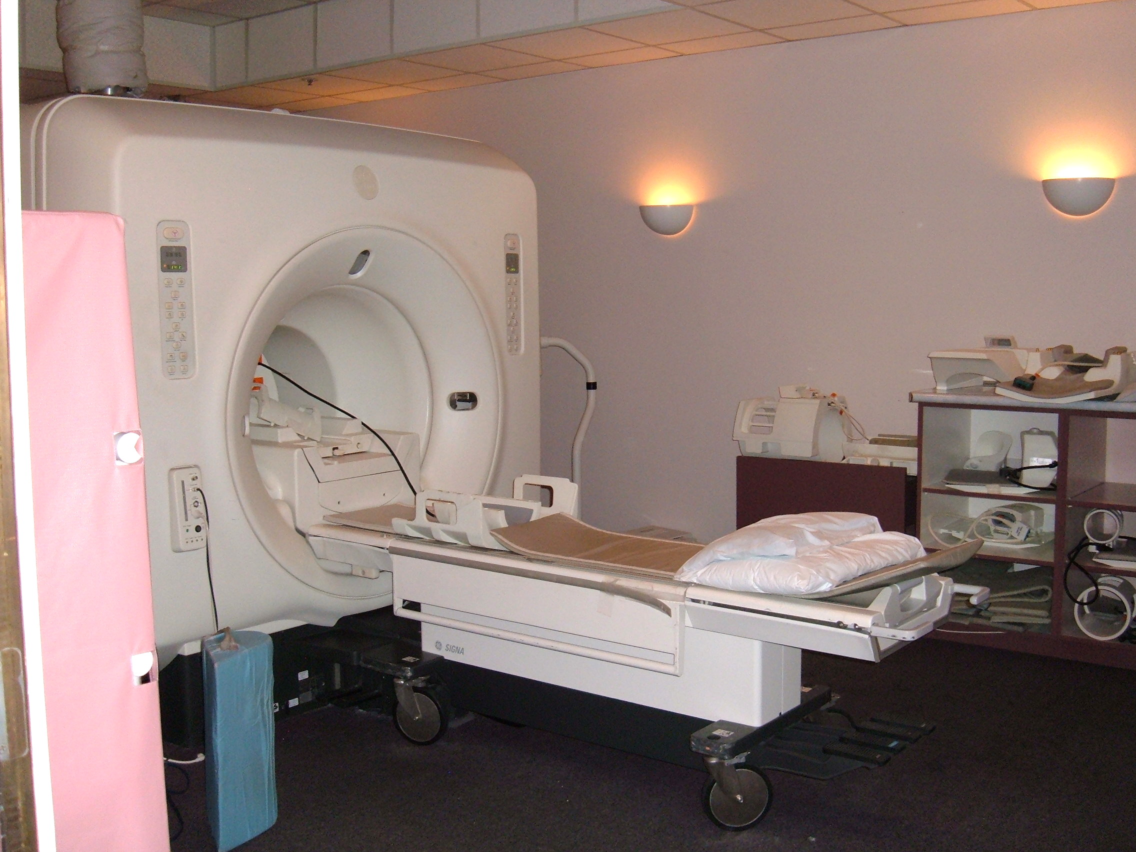
Figure 17:Cerebral angiography, injection in the left vertebral artery, with retrograde flow in the contralateral vertebral artery, the basilar artery and the posterior communicating artery. The posterior cerebral circulation can be seen, including the posterior part of the Circle of Willis. Image courtesy of BrokenSphere, CC BY-SA 3.0, via Wikimedia Commons, accessed here on 2026-02-04.
Inside of an MRI machine has 3 different types of electromagnets:
The main component is a large hallow cylindrical superconducting magnet,
Gradient coils (electromagnets) to shape field, and
Radio-frequency coils (antennas) to transmit high-frequency electromagnetic fields to excite nuclei.
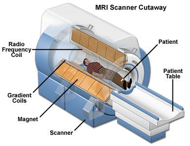
Figure 18:The internal of an MRI machine has 3 kinds of electromagnetic coils: the main magnet, the gradient coils, and radio frequency coil. Image courtesy of Prof. Terry M. Peters at Robarts Research Institute, Canada.
MRI scanning and Metal
MRI, however, is not compatible with ferromegnetic materials, thus it is unsuitable for patients with metallic implants. Care must be taken not to bring ferromagnetic objects near the scanner during the operation as they can be foicibly attracted by the strong magnetic fields.
Applications
Applications of MRI include cardiovascular, brain, spine and joint imaging, where it may be used to discriminate between subtle variations in soft tissue with excellent spatial resolution. Other applications include the detection of intracranial tumours, knee cartilage tears, lumbar disc disease and the staging of malignant tumours. It is also possible to add contrast agents including intravenous gadolinium to reveal tissue perfusion, soft tissue tumours and perform Magnetic resonance angiography.
Figure 19:Time-of-flight Magnetic resonance angiography at the level of the Circle of Willis. Image courtesy of SBarnes, CC BY-SA 3.0, via Wikimedia Commons, accessed here on 2026-02-04.
Functional MRI
Functional MRI measures brain activity by detecting changes associated with floor flow.
Figure 20:An fMRI image with yellow areas showing increased activity compared with a control condition. Image courtesy of OpenStax, CC BY 4.0, via Wikimedia Commons, accessed here on 2026-02-04.
- Elson, D., & Yang, G.-Z. (2010). The Principles and Role of Medical Imaging in Surgery. In T. Athanasiou, H. Debas, & A. Darzi (Eds.), Key Topics in Surgical Research and Methodology (pp. 529–543). Springer Berlin Heidelberg. 10.1007/978-3-540-71915-1_39
- Bushberg, J. T., Seibert, J. A., Leidholdt, E. M. Jr., & Boone, J. M. (2020). The Essential Physics of Medical Imaging. Lippincott Williams & Wilkins (LWW).